Cylindrical Surface Inspection
Not all surfaces respond similarly to standard direct illumination techniques. Surface color, texture, shape, and composition can all influence where and how much of the incident light is reflected into a vision camera, greatly affecting the inspection results.
For example, when examining print for OCV or OCR applications, a particularly difficult application is to uniformly and consistently illuminate the surface of a highly specular cylinder for print OCR.
Testing Coaxial Lighting Geometry
In this example, we’re inspecting a metal automotive inline fuel filter. The print is a dot matrix type using black ink, and the printing direction is parallel to the cylinder’s long axis.
Most print reading applications are set up using a standard coaxial lighting geometry. The camera is positioned perpendicular to the print, and the lighting is a typical coaxially mounted directional ring light. This 3D
camera–object–light geometry works well if the object is composed of a diffuse, non-reflective material, and is relatively flat. However, in this instance, the surface is not only specular but also curved in one direction. Using the typical coaxial geometry, as depicted in Fig 1A, produces an unsatisfactory, non-uniform image (Fig. 1B).
In the case of the set up depicted in Fig. 1A, the 3D envelope that includes the spatial relationships among
camera–object–light is really a 2D geometry, because the light is coaxial with respect to the camera. As the
camera–object orientation must remain the same to maintain image perspective, it would be appropriate to explore changing the orientation of the light, relative to the camera and object.
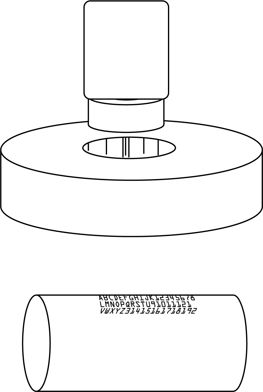
Figure 1A
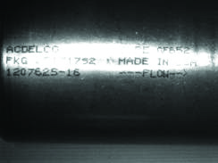
Figure 1B
Adjusting Camera – Object – Light Geometry
Moving the ring light off-axis away from the camera, but along the cylinder’s direction of curvature (Fig. 2A), generates a slightly improved but still similarly unsatisfactory image (Fig. 2B). The image may be readable in its present form, but this geometry does not allow for any difference in object or feature placement, particularly rotational; this is not a robust image.
Let’s examine the 3D geometry in more detail. In the case of Figs 2A and 2B, though we have changed the camera–light geometry, we have not significantly changed the object–light geometry with respect to the cylinder axes.
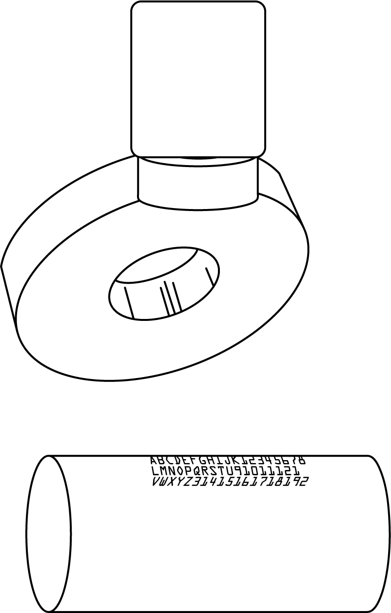
Figure 2A
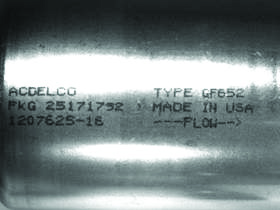
Figure 2B
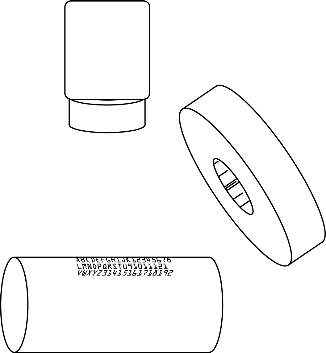
Figure 3A
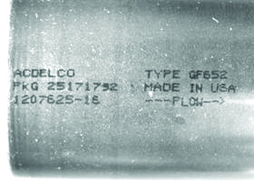
Figure 3B
Thus, by moving the light both off-axis from the camera and off-axis to the object, while remaining coplanar with the cylinder long axis, we generate a consistent, uniform, and robust image (Figs. 3A & 3B).

Figure 4A
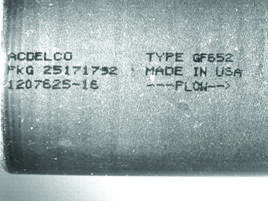
Figure 4B
One consequence of moving the light off-axis (i.e. out of the coaxial position) is a certain loss of maneuvering room near the object.
This can be overcome by using a high-current, high-brightness Spot Light such as the AL143, at a longer (2x or greater) working distance, but in a similar geometry (Figs. 4A & 4B).
Ai Solutions for your Machine Vision Needs
Are you challenged with a cylindrical inspection application and need assistance finding a machine vision solution? We’re here to help! Our team of technical experts are here to work with you to provide the best LED lighting solution for your inspection challenges. Reach out to our team today!