
Lighting plastic lids for surface print and/or screening inspections can be challenging. Plastic lids come in a variety of surface textures, reflectivity, color and orientations. The differences in sizes and quantities of the lids – all potentially running at different speeds and feeds – may also present challenges that may affect the choice of lighting geometry in a plastic surface inspection.
Standard Vision Geometries with Non-Reflective Lids
In an ideal case, we can inspect a singular, small, non-reflective lid for printing or screening defects under a standard vision lighting geometry. More specifically, an illumination geometry with a coaxial light oriented around the lens and pointed perpendicular to the lid surface from a medium working distance, typically less than 20 inches (Fig. 1a).
However, few if any plastic lids are non-specular, so a coaxial light geometry typically produces unsatisfactory inspection results (Fig. 1b).
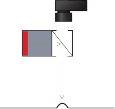
Figure 1a
Coaxial Light Diagram
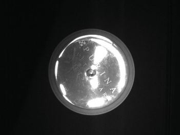
Figure 1b
Coaxial Light Geometry Image
Criteria to Consider for Proper Machine Vision Inspection
Flat, reflective surfaces with topography may respond to diffuse lighting techniques well enough to accomplish the inspection goals. However, there are two important criteria for proper application of a Diffuse Flat, Dome, or Cylinder Light:
- the light must be close to, and directly over, the part
- the camera must also be close to the light to view without “portholing”, requiring the lens focal length to be considered (Fig. 2a).
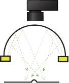
Figure 2a
Diffuse Dome Diagram
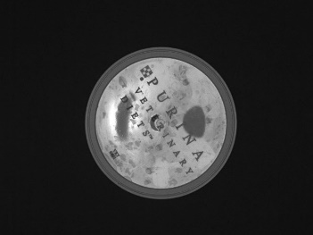
Figure 2b
Diffuse Dome Geometry Image
In this example, the near proximity of the light may limit the access of robotic arms or operator-in-the-loop functions. While the diffuse dome light works well for differentiating the edge from the center flat areas, in this instance it does not produce an evenly reflective surface for effective print inspection (Fig. 2b).
Solution: Proper Geometry for Plastic Lid Inspection
Thus far we have discovered that neither lighting technique – partial or full bright field – are particularly effective on this common plastic lid part, primarily because of nonuniform reflection from a high angle. Are there other choices?
Of the available techniques, we might test a dark field geometry and a medium angle, off-axis bright field geometry. Remembering the low angle geometry from the dark field light function diagram, we see that the majority of the incident light reflecting from the part’s specular flat surface will not reach the camera. However, with this geometry we cannot view the surface for print inspection because the surface is dark, hence the term, “dark-field.”
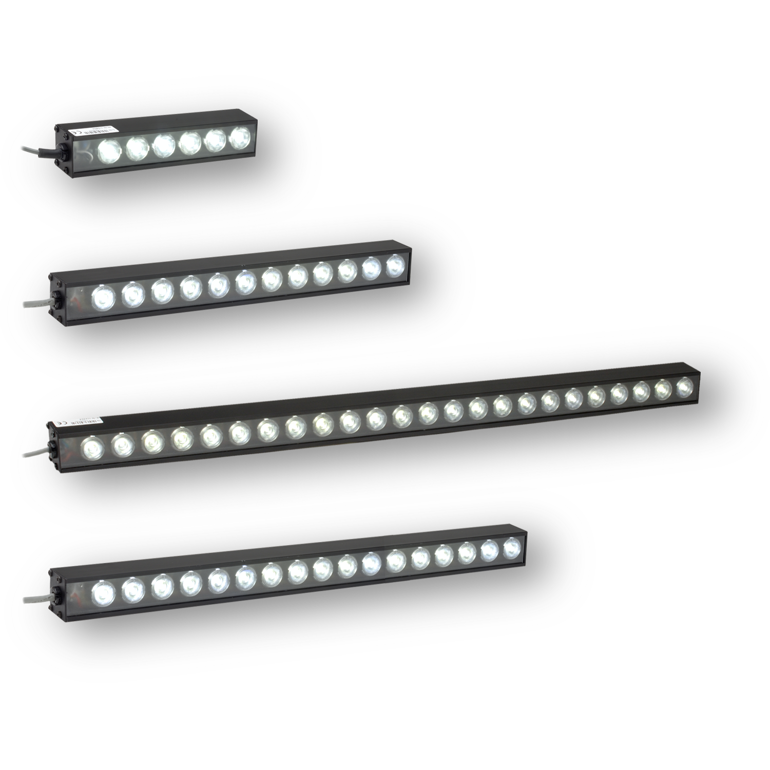
Figure 3a
LL174 Series
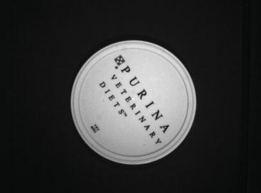
Figure 3b
Opposed LL174 Series
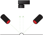
Figure 3c
Off-Axis Bright Field Diagram
This leaves us with the choice of medium angle bright field lighting, which will negate the specular reflection while still allowing for the surface print inspection.
If we examine an image taken using two opposed high-current Bar Lights, using the LL174 Series as an example (Fig. 3a), we see that this lighting geometry is effective for properly illuminating the surface of the lid for print verification (Fig. 3b). Ultimately, we’ve borrowed from a dark field technique that directs the higher angle specular reflections away from the camera, while still allowing for the lower angle reflections to be collected – thereby effectively lighting the surface. We also have better part access with this lighting geometry because of the relatively remote location of the high-current lights.
Scalability for Your Inspection Application Solution
One final benefit of this opposed off-axis geometry: it offers flexibility for inspecting larger sizes and/or a greater number of lids, simply by using longer standard Bar Lights.
Figure 4a is an example of using the longer version of the Bar Lights seen in Figure 3a. The high-current LEDs used in the expandable LL174 Series lights are also well-suited to strobing in high speed applications for even more intensity.
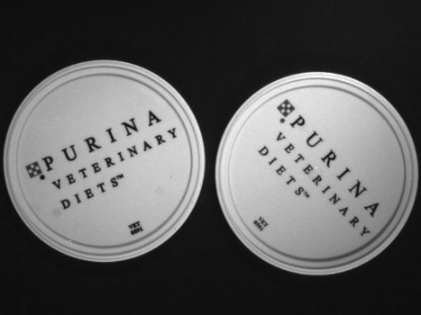
Figure 4a
Opposed LL174 Series
Ai Applications Lab- Your Source for Lighting Geometry Information
As demonstrated in our 4 Cornerstones of Illumination, the 3-D spatial relationship among the light, camera, and part geometry is crucial in solving some of the most challenging machine vision applications. Our team is here to help you: our Applications Lab will work with a sample you send in, recreate your illumination circumstance, and work with you to find the best available solution. Contact us today for expert assistance!