Lighting Technique: Using Polarizing Filters in Machine Vision
While developing an effective and robust vision lighting solution, machine vision engineers often face a near-universal obstacle on the plant floor: unwanted glare. This glare typically comes from the very parts intended for inspection or their immediate background, but it can also be from factory overhead lighting, dedicated task lighting or even natural sources. For purposes of this discussion, we will concentrate on reducing glare from the vision lighting, particularly from a part’s curved, specular surface, which is one of the most common application uses for polarizing filters.
Unwanted Glare: Finding a Better Solution
Before the advent of structured and multiple geometry lighting, the solution to unwanted glare was to employ a set of polarizing filters. One filter, known as the polarizer, is attached to the light, and the other, known as the analyzer, is attached to the camera lens (Fig. 1). Both pieces are composed of the same linear polarizing material, but they are named differently based on their position in the optical path. Following tradition as well as ease of use, the analyzer typically is rotated relative to the polarizer, in the hopes that the reflected light producing the glare would be blocked from passing into the camera lens by the analyzer.
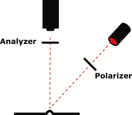
Figure 1 – Typical Vision Polarization
Limitations with Traditional Polarizers
This solution can be effective; however, there are limitations. When rotating 1 of 2 stacked polarizers, the light transmission varies between maxima and minima every 90 degrees of rotation (360 degrees being 1 rotation). In the case of transmission minima, we are near full extinction, and very little, if any light is passed (< 3% Fig. 2a – center area) – making it unsuitable for many vision inspections.
And even at transmission maxima we see, at best, partial transmission (30% Fig. 2b – center area). This results in a less than effective solution – even when the glare is effectively blocked at transmission maxima, particularly in high-speed applications.
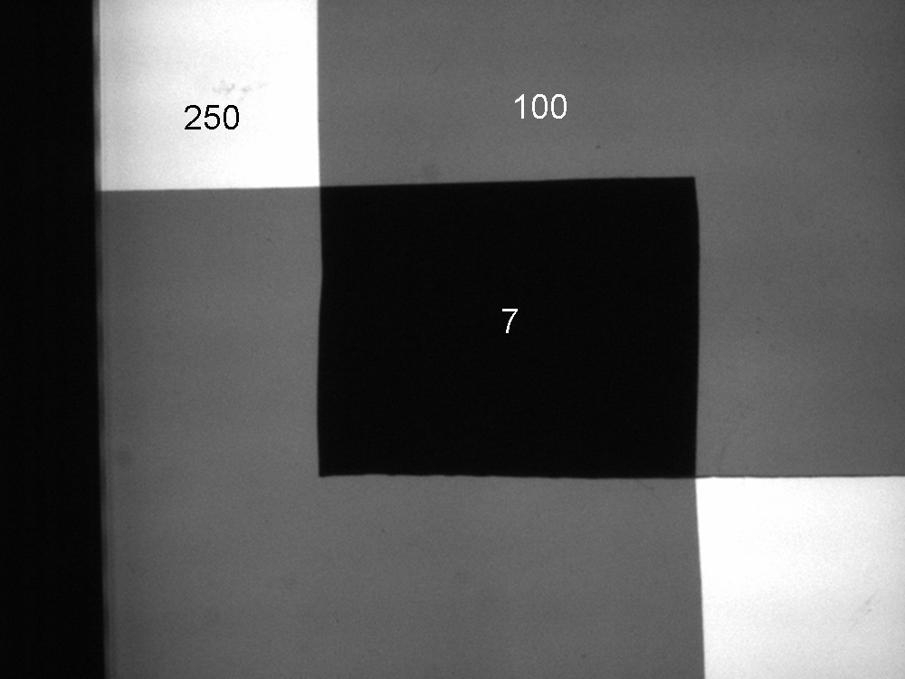
Figure 2a – Crossed Polarizers: minima over a red backlight. Values represent intensities; lightest areas have no polarizer cover.
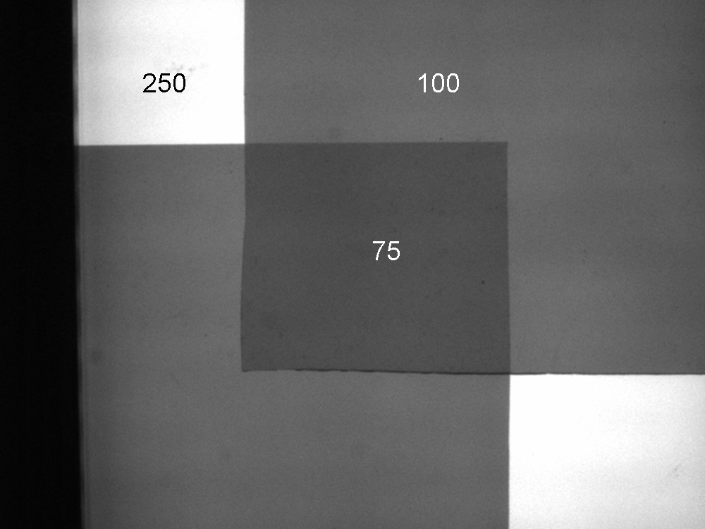
Figure 2b – Crossed Polarizers: maxima (rotated 90 degrees from those in Figure 2a).
Solution #1: Cross-Polarized Ring Light
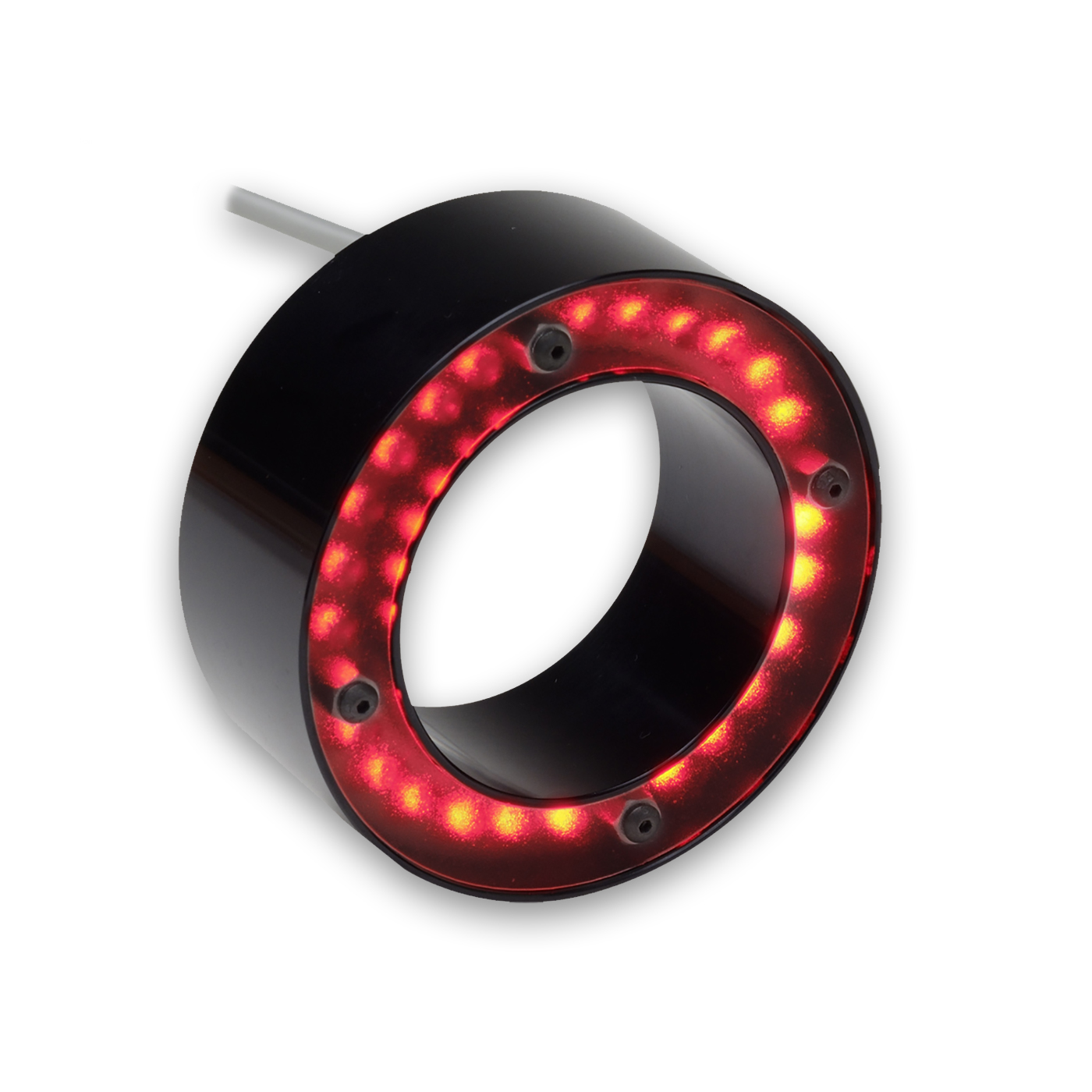
Figure 3a – Coaxial Ring Light Geometry, No Polarizers
Given the above comments regarding low light levels when polarizing, even under the best of conditions, parts moving at relatively high line speeds obviously require more light to compensate for the correspondingly shorter sensor exposure times necessary to freeze part motion to 1 pixel value or less. The following example, utilizing a cross-polarized ring light (see Fig 3a, RL1424-660 example), provides an effective and robust inspection result of the lid printing.
In this example, we see that in a standard coaxial lighting geometry (ring light around a lens, both mounted perpendicular to the part surface), unpolarized light (Fig 3b) that reflects off the planar, perpendicular surface of this jelly lid as unwanted glare is entirely negated, when polarized (Fig 3c), providing for a effective and robust inspection of the lid printing.
Consider, however, that to retain the same general scene illumination intensity between non-polarized and polarized light, the lens aperture was opened 2½ f-stops, which may be an issue in a relatively high-speed, light-starved application.
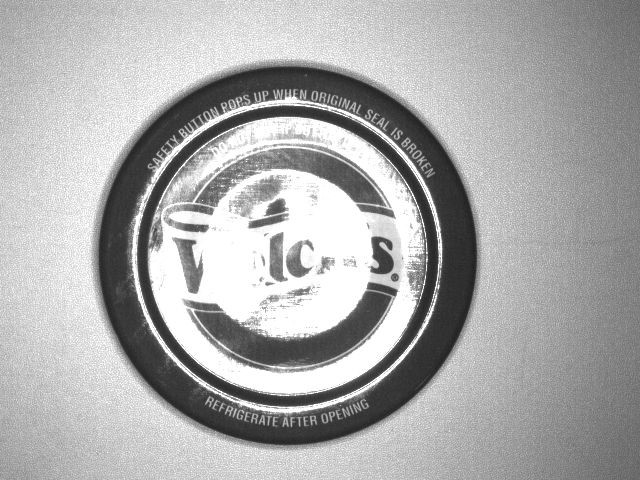
Figure 3b – Coaxial Ring Light Geometry, No Polarizers
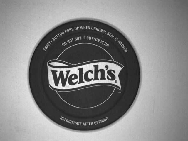
Figure 3c – Same Geometry with Polarized Light. Note: Lens Aperture Opened 2 1/2X
Further, it is noteworthy that even with a single polarizer (no analyzer in the optical path), light transmission is decreased to 40% of the total available light. As an aside, the use of a single polarizer in many cases acts as a reasonable Neutral Density (ND) filter.
Finally, with the advent of very high-output LEDs, especially lens-concentrating versions, the standard acetate plastic film linear polarizer material is subject to thermal and energy absorption breakdown, in some instances in as little as 100 hours of exposure. Recent anecdotal evidence and testing data confirm that both heat and shorter wavelength light (blue and shorter) adversely affect polarizer longevity, specifically burning spots in the materials in front of the LED lens.
There are several solutions commercially available to combat this issue, including higher-temperature robust plastics, as well as glass sandwich and even wire grid polarizers. Whereas these materials generally offer better performance against heat and shorter wavelength polarizer degradation, some are particularly expensive and more difficult to adapt to the many sizes and shapes needed to fit light heads.
Improved Solutions with Adjusted Lighting Geometry
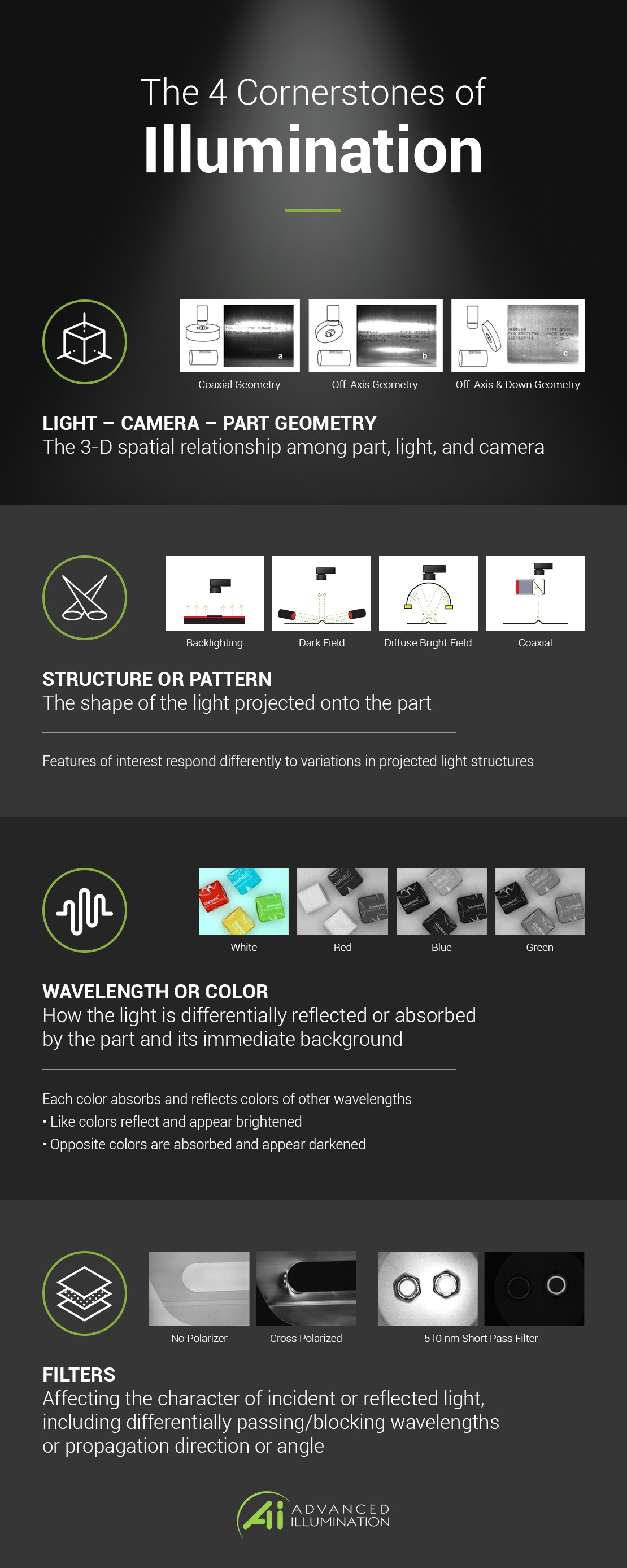
Rather than utilizing polarization to combat part glare, there may be a more effective solution: modify the lighting geometry, or the 3-D spatial relationship among the part, light, and camera. In the following example, we will investigate the use of standard polarizers versus a change in lighting geometry to obtain an acceptable image for inspection.
This sample part is a bottle of styling gel, which is composed of clear plastic, is reflective, and curved – in both directions. With these particular characteristics, we might expect to generate a large amount of reflective glare on this type of surface, depending on the lighting type and geometry used.
Figures 4a and 4b depict the bottle in the same common coaxial light geometry as the jelly lid part from Figure 3 above without and with polarizers, respectively. As might be expected, this configuration without polarization (Fig 4a) exhibits considerable glare reflection directly from the coaxial ring light.
We can see that the image in Figure 4b shows considerably less glare under crossed polarizers, but some glare is still apparent. Whether cross-polarization is an effective and robust solution, depends on if the glare obscures features of interest in this image, or as importantly, in the next bottle’s image.
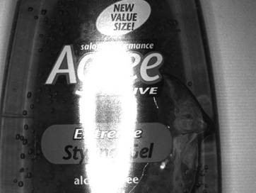
Figure 4a – Coaxial Ring Light, No Polarizers. Note: 2 F-Stop More Light Required

Figure 4b – Coaxial Ring Light, Polarizers.
One important note in this lighting solution: the lens was opened by 2 f-stops to get approximately the same illumination level into the camera. Additionally, because the bottle is curved in 2 directions, it is not possible to “dial” out all the glare with a polarizer / analyzer combination, compared to the planar surface of the jelly lid example above, for example.

Figure 4c – Ring Light Off-Axis, No Polarizers
However, if we now change lighting geometry by moving the ring light off-axis with respect to the camera and lens, but in the direction parallel to the bottle’s long axis, we generate the image depicted in Fig. 4c. As you can see, this change in lighting geometry results in an image free from any remnants of glare – and there is no polarization effect restricting the illumination intensity. The off-axis ring light is an acceptable solution, so long as the light can be relatively close overhead, but it must be oriented pointing parallel to the bottle long axis in this instance. Should this geometry be unavailable due to access limitations, are there other geometry/structure solutions available?
Additional Solutions to Reduce Glare in Machine Vision
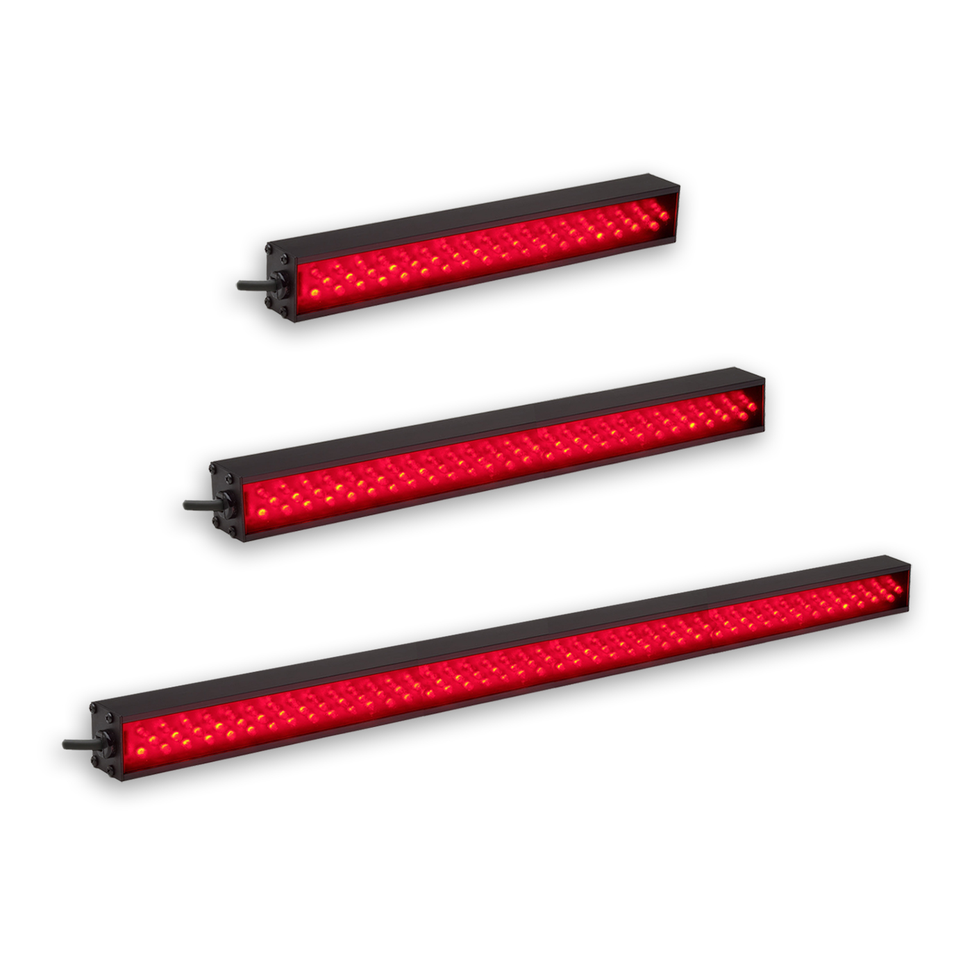
Figure 5a – AL150 Series, Including AL4424-660; Red BALA

Figure 5b – BALA; Longitudinal Orientation
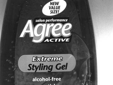
Figure 5c – BALA; Transverse Orientation
To test this idea, we investigate using a Broad Area Linear Array Light (BALA), AL4424-660 (See Fig. 5a) in both the longitudinal (Fig. 5b) and transverse (Fig. 5c) orientations. The results illustrate that the transverse BALA orientation works as well as the off-axis ring light.
What advantage does the BALA orientation confer? It can be mounted from farther away and at a lower angle from horizontal, thus allowing the near overhead area to remain open, unlike the ring light. Additionally, it does not have to be mounted in a coaxial position, which can also be advantageous if the close positioning of the camera and lens limits light accessibility. Fig. 5d illustrates the BALA light function diagram.

Figure 5d – BALA Light Diagram
Other Uses for Polarizers
Are there additional appropriate uses for polarizers in vision?
A common use is to detect physical anisotropies in transparent and translucent materials, such as plastics. For example, Figures 6a and 6b are back-lit images from polypropylene film, with and without polarizers, respectively, illustrating the strain field in what otherwise looks like normal plastic in non-polarized backlighting.
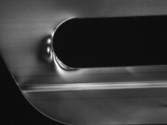
Figure 6a – Plastic with Polarized Backlight
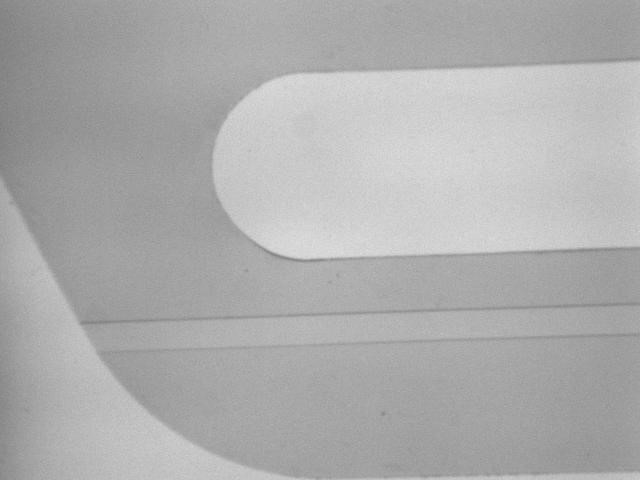
Figure 6b – Plastic without Polarized Backlight
In conclusion, polarization in machine vision can be effective, given an understanding of its application limitations and conditions. In general, modifying the lighting geometry is a preferred solution to minimize glare, when possible.
Need help with a solution that might require polarization? Interested in learning more about how an Advanced illumination light can be used in your application? Reach out to one of our knowledgeable representatives today!