Determining whether to apply lights in a bright field versus dark field geometry is one of the more difficult decisions facing Machine Vision engineers. Bright field lighting is the more commonly applied lighting geometry, which involves mounting and orienting lights between 90 and 45 degrees from the imaging surface (off horizontal). Conversely, dark field lighting involves orienting lights between 0 and 45 degrees off horizontal, which is particularly effective when imaging highly reflective surfaces or generating edge effects.
Both techniques have advantages and disadvantages: whereas bright field (BF) lighting is a more common application for most inspections, dark field (DF) lighting has a more specific and limited set of requirements for its successful application in dark field inspection. We will concentrate on a comparison between the two using common vision applications.
Bright Field Illumination Technique
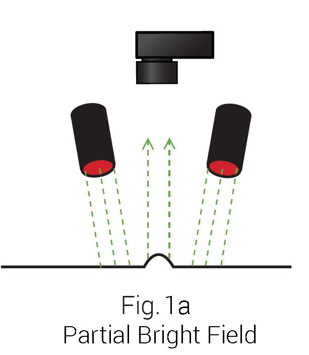
Bright field can be divided into two sub-techniques, differentiated primarily by solid angle, which is generically defined as a measure of the amount of relative area from which the light is sourced:
- Bar Lights, Spot Lights and Ring Lights, or any light at a significant working distance (WD) with a relatively small solid angle, are termed Partial or Directional Bright Field point sources (Fig. 1a).
- Conversely, large solid angle hemispherical or planar lights, such as Diffuse Domes and Cylinders (Fig. 1b), or Coxial Diffuse (Fig. 1c) and “Flat” Arrays, are all termed Full Bright Field sources.
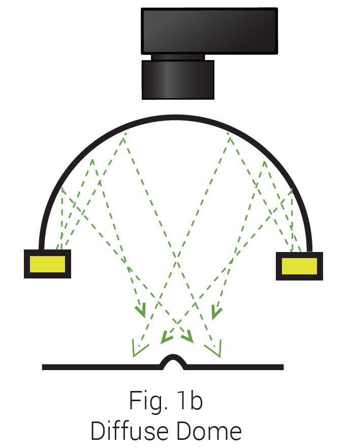
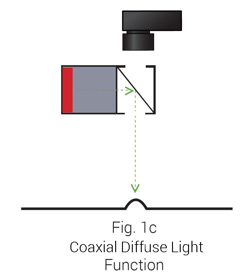
It’s important to consider that in general, Full Bright Field lights are most effective when placed relatively close to the intended inspection surface, as they subtend a larger solid angle. This creates a more diffuse light projection, which assists in inspecting reflective or widely different surface textures and elevations.
For the above reason, it’s important to note that as any light’s WD increases, its solid angle decreases. This renders the Full BF light’s diffuse and multiple angle light geometry effect more typical of a Partial BF light. Why is this dichotomy important? Simply because each combination of light presentation, geometry, WD, and solid angle has its own advantages – which depend on the inspection part’s characteristics, features of interest, and part access considerations – just to name just a few.
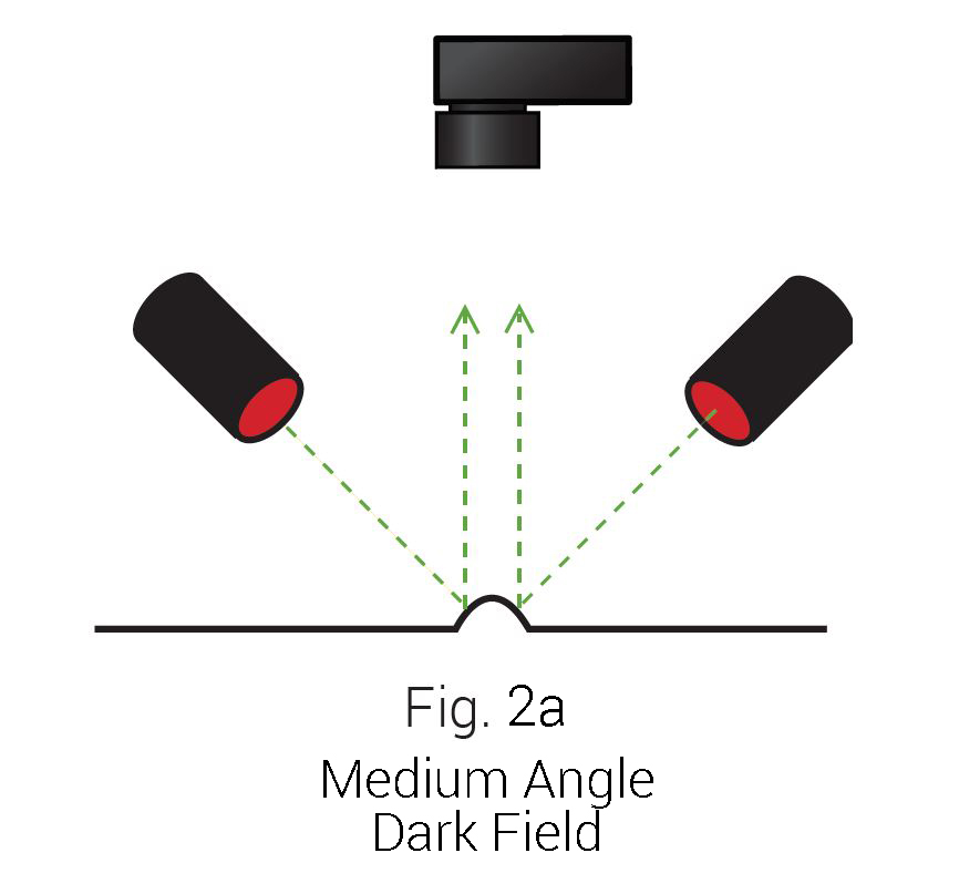
If a bright field is characterized as the result of high angle incident light producing a “bright” field of view, then we might conclude that dark field lighting would generate a primarily “dark” field of view at low angles of incidence (Fig. 2a). How can this be? How can light produce a “dark” field?
Dark Field Lighting Technique
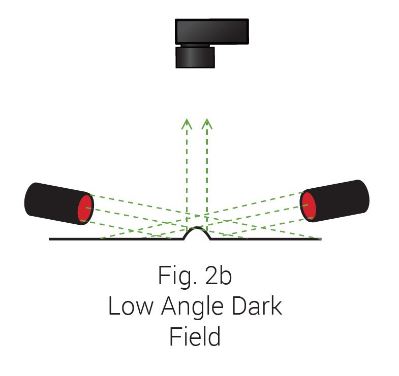
Dark field lighting was first applied in microscopy and was defined by circular light incident on a surface at approximately a 45 degree angle. As commonly used in machine vision today, we also see very low angle DF with incident light as low as 10-15 degrees from the surface (Fig. 2b), as well as from a single direction – and not necessarily just from circular (e.g. – 360 degree) sources.
Figures 3a and 3b illustrate the results of how BF and DF light responds differently on a flat, mirrored surface.
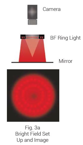
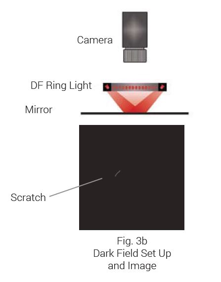
To fully understand how dark field light is produced and used, it is important to remember a simple physical property of incident light: the angle of reflection is equal to the angle of incidence. Furthermore, it is the actual detail of the surface features that determine how and where light reflects (scatters).
If we examine the angle of incidence in Figures 3a and 3b, then similarly project what the angle of reflection would be, we can start to understand how a dark field is produced.
For example: if our camera collects the light from a high-angle bright field ring light reflected from the mirrored surface, we see that most of the light is reflected into the camera. This effect produces the image we see in Fig. 3a, typically referred to as a specular hot spot – in essence, we are imaging the light source.
Now, we’ll compare the amount of projected light from the low angle DF ring light in Fig. 3b. We can clearly see that most of the light reflects away from the camera, and is therefore not collected, hence we see a “dark field”. Naturally this begs the question – how is this effect useful?
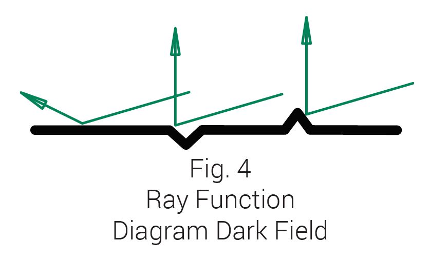
Consider the previously discussed physical property of reflected light: reflected light propagates away from the mirror at the same angle at which it was incident, and in the case of relatively low angles of incidence, it’s not reflected back into the camera. However, the scattered light off any individual surface detail that does happen to reflect into the camera produces what might be termed feature-specific contrast (Fig 4). Using this technique, we can effectively inspect a mirrored reflective surface for defects, or read/verify a bar code beneath a specular reflective plastic cover – both otherwise unreadable using standard bright field lighting.
Examples of Bright Field Illumination vs. Dark Field Illumination Techniques
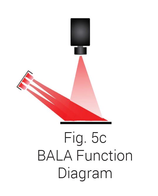
Figures 5a and 5b illustrate another example of the robustness of dark field vs. bright field lighting for some common inspections. The image in Fig. 5a was captured with a standard coaxial-oriented (a.k.a. – on-axis) Bright Field Ring Light, whereas the image in Fig. 5b was generated by a Linear Bar Light (Fig. 5c – AL4424-660 BALA), oriented from the side in classic dark field geometry.
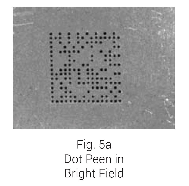
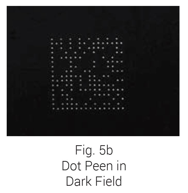
While either image is likely suitable as-is, consider if the next part had significant dark staining. The DF image likely would not change, whereas the BF image may make the stain plainly visible, and depending on the stain’s severity, could affect the inspection results.
Can it then be assumed that all dark field lights are applied at very low angles of incidence to produce a completely dark field, except for surface abnormalities? No. In the following example, we see that using a light off-axis near 45 degrees allows us to take advantage of the dark field effect – erasing a specular glare problem.
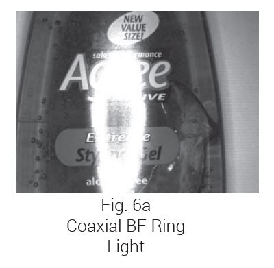
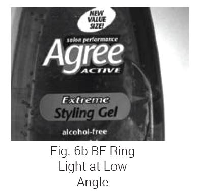
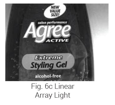
The series of images in Fig. 6 illustrates the effect of applying both Ring and Bar Lights at an angle that allows the majority of light to reflect away from the camera for dark field lighting. This geometry eliminates specular glare while still allowing enough captured field lighting to view the surface label and details.
The image in Fig. 6a shows specular reflection of a coaxial orientation Bright Field Ring Light. Compare this image with that in Fig. 6b where the same light was moved off-axis to produce an acceptable result for inspection. Similarly, if part access is limited, a High Intensity Array Light may be mounted transversely to the bottle length from a greater WD to produce the same acceptable inspection result (Fig. 6c).
What to Consider When Using Bright Field Lighting vs. Dark Field Lighting
We have compared the application and results of bright and dark field lighting geometries, but there are some usage criteria to consider for each
Directional or partial BF lights are the most versatile from a positioning standpoint, so long as they don’t produce specular glare. For example, try imaging the surface of a ball-bearing with a ring light. Full BF lights, particularly the Diffuse Dome and Cylinder varieties generally need to be positioned in close-proximity to the inspection surface and may need to be selected with specific lenses in mind. These considerations are both to avoid vignetting issues while considering the possibility that these lights may block part access – particularly important in a vision-guided robotics implementation.
Dark field lights – particularly the circular varieties – must also be placed very close to the part, potentially suffering similar problems as full BF lights. Assuming circular DF lights are not necessary, Bar Lights with sufficient intensities can be placed in a dark field orientation from a longer WD, alleviating some part access issues. With the exceptions of Diffuse Area Lights and Back Lights, almost any light can be used in a dark field orientation.
Specifying the Correct Lights for Your Bright Field or Dark Field Illumination
Whether your machine vision lighting application requires dark field or bright field illumination, we have a variety of LED lighting options to meet your challenges. Browse our lighting products or reach out to our team of experts to assist you in finding the right solution for your BF or DF lighting application!

