
Packaging inspection has typically presented a variety of challenges for machine vision developers and integrators alike. This is primarily because of the wide range in types of packaging – materials, colors, sizes, shapes, and textures used. Additionally, limitations to part access for vision equipment and line speeds and feed rates pose challenges.
One typical packaging application is inspecting for the presence or absence of objects, which have been either purposely or inadvertently inserted into packaging containers.
Finding Object Presence in a Metal Container
This specific vision inspection includes verifying the presence of a plastic powder scoop purposely inserted into an empty metal can before the powder is added and the container is sealed (Fig. 1a).
As is true for most all vision inspections, there are several issues to consider when determining appropriate lighting:
- limited access to the open can
- the differential reflectivity of the metal can bottom, sides, and the plastic scoop
- the size and depth of the can.
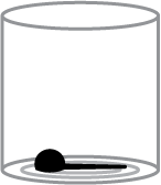
Figure 1a
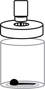
Figure 1b
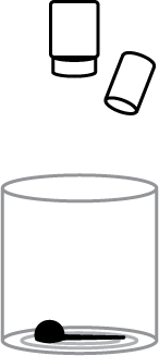
Figure 1c
Because the viewing angle for this type of inspection is limited, one of two possible lighting geometries – both direct point sources – is typically employed. These lighting geometries include a Coaxial-oriented (on-axis) Ring Light (Fig. 1b) and an off-axis Spot Light (Fig. 1c). If sufficiently focused, the Spot Light has the advantage of being deployable at a longer working distance when access directly above the container opening is limited.
Remember that the goal of this inspection is to verify the presence of the scoop uniquely in the can.
If we examine images captured from the off-axis Spot Light and Coaxial Ring Light geometries, we can visually determine the presence of the scoop, but neither image is particularly appropriate for a vision system inspection (Figs 2a & 2b). This circumstance is primarily the result of differential reflectivity from the metal can interior and the plastic scoop, along with the lack of light uniformity, incident on all the surfaces.
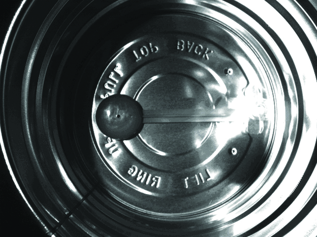
Figure 2a
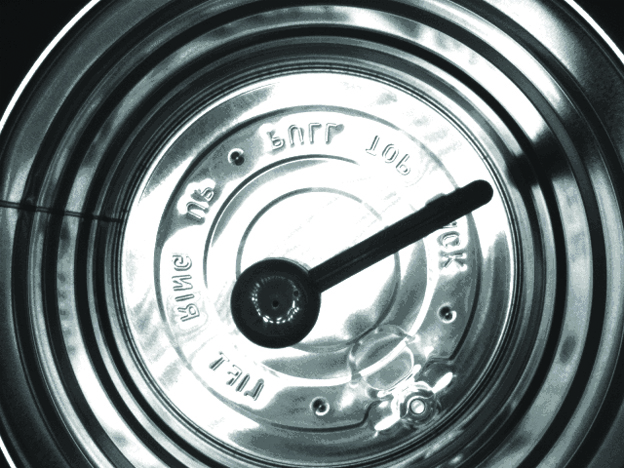
Figure 2b
However, if we agree that a Coaxial geometry is the most appropriate, but we have ruled out a direct point source such as a Ring Light, what are the remaining choices? Given the limitations of this inspection, specifically viewing access to the features-of-interest – the scoop, we are restricted to two other possible Coaxial lighting techniques: Dark Field and Full Bright Field Diffuse.
Dark Field and Full Bright Field Diffuse Lighting for Presence/Absence Inspection
With a few exceptions, it is important to note that one of the limitations of both Dark Field and Diffuse lighting is that the light is most effective when mounted relatively close, and often perpendicular to, the part of interest. For purposes of this discussion, we will orient the inspection to be top-down into the can, with the camera mounted directly above the opening.
Further, assuming top-down access is not a restriction, we see that the image from a Dark Field Ring Light, with incident light from a 45-degree angle, offers better uniformity than the standard High-angle, Bright Field Ring Light. This is primarily because the light is effectively “bounced” or scattered around the container, being incident on the can sides at 45 degrees (Fig. 3).
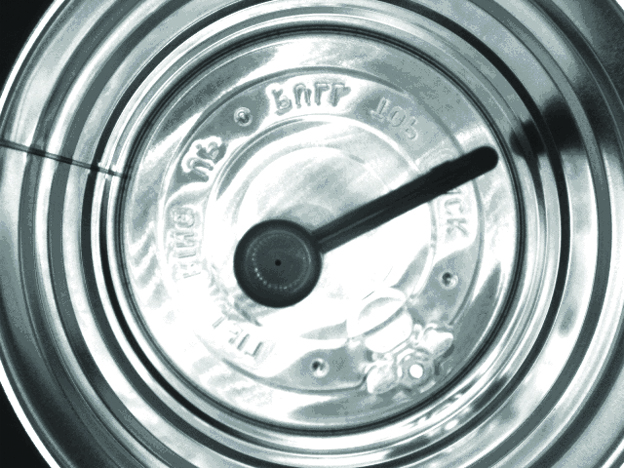
Figure 3

Figure 4a
However, are we fully utilizing the capabilities of the Dark Field Ring Light in this particular geometry? Is there still a better, more appropriate solution?
It is useful to note that Full Bright Field lighting differs from partial or direct point source Bright Field, because it is uniform and typically diffuse in nature. The light can be multi-directional, such as from a Dome Light, or unidirectional from a wide area source, such as a Coaxial Diffuse Illuminator. Because we already suspect that multi-directional light like that from the Dark Field Light is not necessarily optimized for this application, we can view the part under the Coaxial Diffuse Illuminator (Fig. 4a).
We can see that the Coaxial image is the most robust in uniformity and feature of interest contrast, regardless of where the scoop is located or how it is oriented in the can. In this instance, we have taken full advantage of the unique attributes of the Coaxial Illuminator “showering” the bottom of the can with light all from the same direction and of the same intensity (Fig. 4b). In this application, the part size required a large Coaxial Diffuse Illuminator, one with a 6” x 6” field-of-view: the DL225-150625 (Fig. 4c).
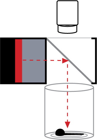
Figure 4b
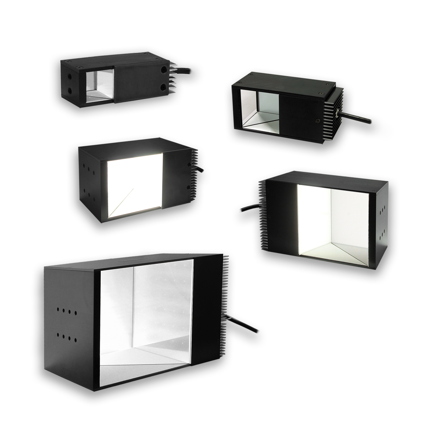
Figure 4c
Challenges in Using Diffuse Illumination
Up to this point, our analysis and discussion have assumed that we have full access to the top of the can opening.
When using the DL225-150 Coaxial Illuminators, one restriction may be its height. This type of light head is typically as tall as it is wide, and in this case it’s around 6” high. If space above the can opening is limited, we would need to try another solution and hope for similar positive results. For situations with limited Z-axis space above the part, we can use the FD0808-660 or the side-fired FX0808-625 Lights – both thin Diffuse Panel Lights – with a Coaxial viewing port (Figs. 5a & 5b) which may achieve a similar, if less distinguishable result.
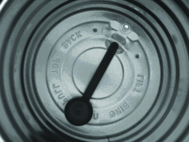
Figure 5a
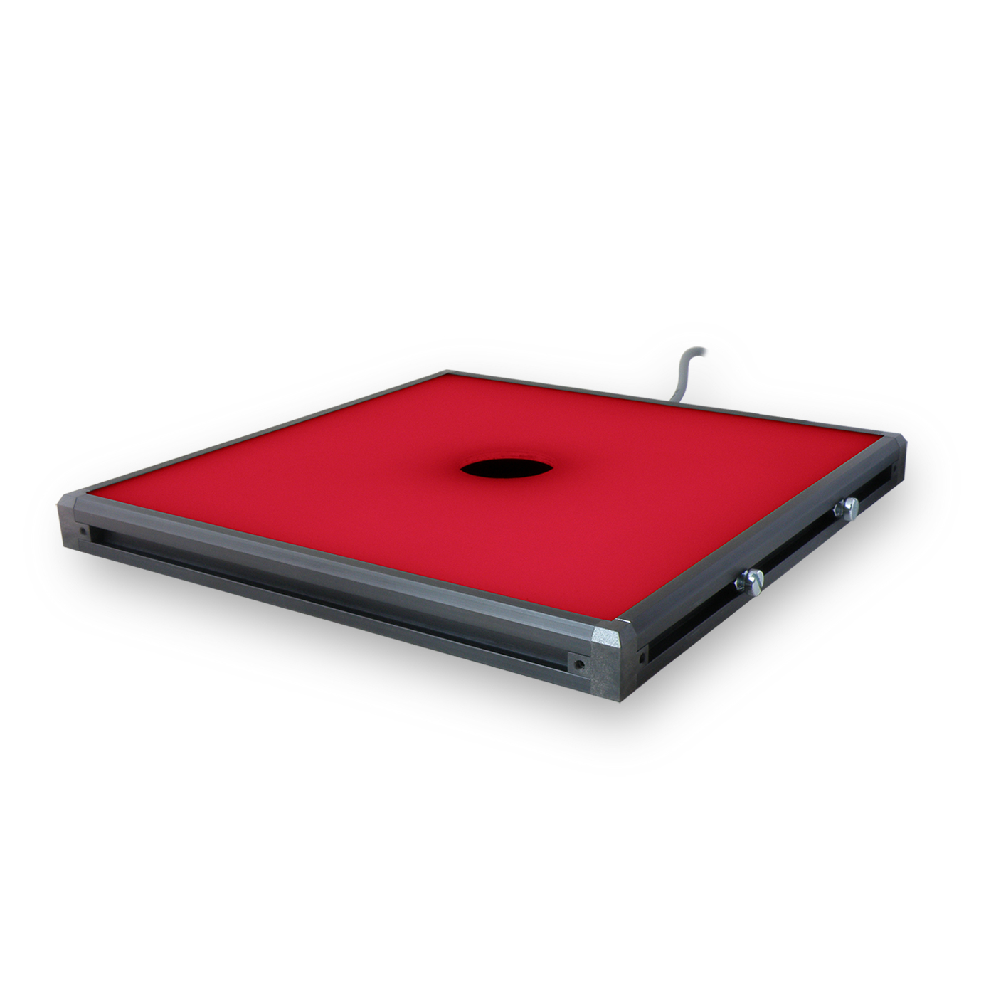
Figure 5b
Be Proactive: Specify Illumination in Machine Vision Systems Early
While there are often challenges in building inspection systems, understanding which lighting geometry or type of LED light to incorporate doesn’t have to be one of them. By considering your source of illumination in the beginning of specifying your machine vision system, you can effectively reduce the challenges you experience, such as part access and overall space limitations. Reach out to our team of experts to assist you in finding the best solution for your illumination challenges!