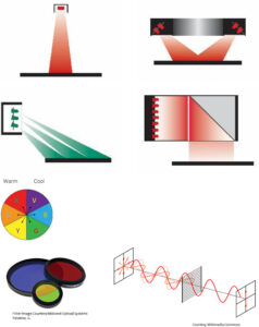
There are four image contrast enhancement concepts (Cornerstones) used for vision illumination: geometry, the spatial relationship between light and object; pattern, or structure — the shape of the light projected on the object; wavelength, or color — how light is differentially reflected or absorbed by the object and its immediate background; and filters, which differentially block or pass wavelength and/or light directions.

These four cornerstones of image contrast were devised as a teaching tool for providing a means of identifying and demonstrating four ways to enhance or create appropriate image contrast of parts against their backgrounds. It’s likely that machine vision system designers have the most control over geometry during the early planning stages of the application. Lighting techniques, however, can easily become the cornerstone with which you have the least control if it’s an afterthought in the project.
Proper planning ensures effective, consistent, and robust features that are optimal for each inspection. Priority of investigation is one of the most frequently asked questions about the concept of the four cornerstones. Would wavelength take precedence over geometry? Is it better to start with structure and then apply filtering?
Honestly, there’s no easy answer. The approach will depend on the part, as well as the expected results for the specific application. For specular surfaces, geometry and structure are more important, while for color and transparency, wavelength and filtering are more crucial.
System Geometry: One Key to Consistent Image Formation
When evaluating the quality and robustness of a lighting system, it is essential to appreciate how the four cornerstones can be utilized to manipulate and enhance image contrast between a part and its immediate background. For many applications, more than one cornerstone is required for optimal image formation.
Geometry is used generically, but it can be useful to distinguish between system geometry and light ray geometry. System geometry refers to the spatial relationship among the camera, the light head, and the object. System geometries can be broadly divided into two categories: Coaxial (on-axis) lighting is the first, and the second broadly defined system geometry is off-axis front lighting.
Coaxial Lighting: Centered Illumination
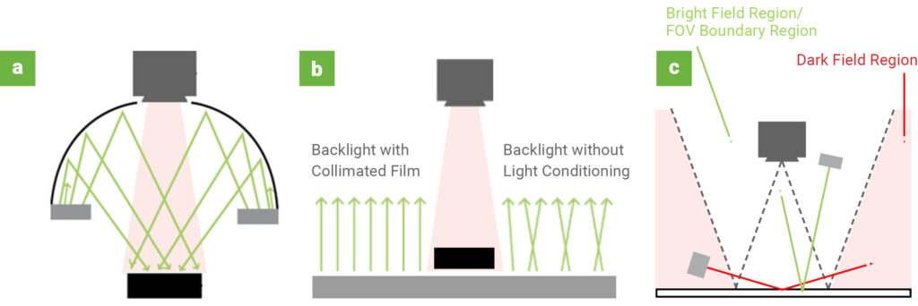
Coaxial lighting is commonly referred to as on-axis lighting since it is centered around the camera’s optical axis. Lighting such as this includes domes and tunnels, flat domes, coaxial and ring lights. As a coaxial variant, back lighting can also be considered (Fig 1). Dome lighting provides illumination similar to that of overcast days. In this manner, glare is minimized since the light comes from a variety of directions and angles.
In order to change the contrast via geometry, the relative position of object, light, and/or camera are adjusted in space until a suitable arrangement is obtained. In general, however, this combination of moves in space works best under partial bright field, directional lighting (learn more about partial bright field lighting). A full bright field, diffuse technique typically requires fixed and coaxial alignment positions between camera/lens and light, limiting the range of movement between the components.

Fig. 1: a – Dome Coaxial lighting, b – Backlighting showing collimation (left side) and Standard Backlighting, c – Off-axis Front lighting with Bright Field and Dark Field modes
The light ray geometry may be related to the system geometry, because certain system geometries produce specific light ray geometries. However, sometimes the same off-axis system geometry can produce a different effect, especially in the case of reflection geometry, on the part or feature of interest (Fig.2).
Off-Axis Front Lighting: The Power of Light Ray Geometry
Off-axis front lighting can be broken down into two subcategories of lighting, partial brightfield and dark field. This type of lighting generally consists of ring lights, spot lights, and bar lights. In particular, the light and the resulting image produced by a coaxial system geometry (camera and light) in an off-axis orientation (Fig. 2a) will differ considerably from both the camera and light in non-coaxial off-axis positions (Fig. 2b).

Fig. 2: a – Off-axis coaxial lighting minimizes specular reflection from the surface, b – Off-axis non-coaxial lighting attempts to gather the reflectivity from specific surface features.
Light ray geometry as depicted in the left graphic in Fig. 2 mitigates surface specular reflection so relevant surface details are visible in an image, whereas the set-up in the right graphic gathers reflections, rather than mitigating them — usually because the surface features of interest are differentially more reflective than the rest of the surface.
Considering the off-axis perspective of the camera with respect to the surface, it is easy to conclude that the inspection type under the system and light ray geometries depicted in Fig. 2 is usually limited to Presence/Absence or perhaps general location, rather than measurements of sizes, shapes, or spatial relationships. On the other hand, a camera that is perpendicular to the inspection surface and the light that is off axis can alleviate surface glare without the perspective shift (Fig. 3).

Fig. 3: a – Coaxial camera alignment, off-axis lighting to reduce glare. Light ray angle of reflection (dashed red arrow) is equal to the angle of incidence on the surface, b – Example of camera and light coaxial alignment illustrating glare reflection, c – Example of camera in coaxial alignment and off-axis light, mitigating source glare reflection, d – Image of the system geometry used to achieve the image in Fig. 3c.
Geometry: The Key to Consistent Performance
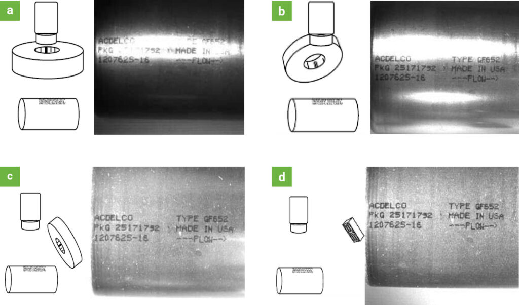
Light head, or lighting technique specific changes via structure (learn more about Illumination Techniques), usually relate to how the light is projected on the part. Object-light interactions are related to contrast changes due to differential color absorption and reflectance. Geometry plays a crucial role in delivering consistent and robust performance on a specular cylinder inspection (Fig 4).

Fig. 4: Lighting Geometry — reading ink print on an inline fuel filter, a – Sandard coaxial geometry, note the hot spot reflection directly over the print, b – Off axis — acceptance criteria is met, but what happens when the print is rotated slightly up or down? c – Off axis down the long axis of the cylinder — all three criteria met, d – Same as in image “c”, but from a longer working distance.
Certain techniques require specific light and geometry, or relative placement of the camera, object, and light; others do not. Diffused dome lights, for instance, are exclusively used in coaxial mount orientations, whereas bright field bar lights may also be used in dark field orientations. Lighting manufacturers usually offer lights that produce a variety of combinations of lighting effects, and LED-based lights may allow each effect to be individually controlled.
In this way, numerous inspections can be completed in a single station instead of two, reducing potential costs. As long as the conditions and limitations of each of these lighting techniques — as well as the intricacies of the inspection environment and object-light interaction — are understood, an effective lighting solution that meets the given acceptance criteria can be developed.
Need help finding a light with the perfect geometry for your application?
Click the button below to talk with our application experts.
