
Compared to today, early machine vision lighting was limited in several ways – there were few choices in source type, style, geometry, and wavelength. Many vision inspections either failed outright or succeeded largely on the only available lighting sources and types available: task-specific fiber-optic or fluorescent lights and/or ambient lighting. Those applications that required more structured, task-specific lighting geometries were typically compromised in some fashion, if they were workable at all.
Today there is a wide variety of lighting sources, types, geometries, and wavelengths available for vision engineers to apply, often with more than one type or geometry functioning adequately. But with the many overlapping choices, how do we determine whether a lighting solution is, or is not, truly “good enough”?
Three Criteria for Successful Inspection Illumination
There are three criteria that may be applied when solving a lighting problem, and all relate to image contrast:
- Maximize contrast on those features of interest
- Minimize contrast on those features (background) of no interest
- Make the solution robust
The ability to make the solution robust is often overlooked, but it is typically the best indicator for whether the lighting solution is merely “adequate” or if it will truly stand the test of time.
For purposes of this discussion, we will consider several examples illustrating the importance of a lighting solution that is not merely “good enough” but is indeed robust. In other words, the lighting solution must be effective and consistent over a variety of part and inspection environment differences, such as shape/size, orientation, color, and presentation, to name just a few.
Example: Reading a Barcode Through Cellophane
Figs. 1A – 1C illustrate a series of images from an inspection system designed to read a barcode beneath a cellophane wrapper. The image in Fig. 1A was generated using a Coaxial Diffuse Light, which is clearly ineffective for reading the bar code because of the specular reflections.
Fig. 1B illustrates the results of applying a Low Angle Dark Field Ring Light; the image is more consistently free of specular wrapper reflections, so the lighting solution could be considered adequate. However, because we have not completely removed the specular reflection, there is still potential for the next part to have an obscured code due to a particularly strong fold in the cellophane wrap.
The image in Fig. 1C shows the same part free of specular reflection, and is thus not only “adequate”, but is in fact more robust. Fig. 1D shows the Broad Area Linear Array Light and its geometry applied to generate the image in Fig. 1C.

Figure 1A
Coaxial Diffuse Light DL225-050

Figure 1B
Dark Field Ring Light DF242

Figure 1C
Broad Area Linear Array (BALA) Light AL150024

Figure 1D
BALA Light Function Diagram
Example: Bottle Inspection with Glare
Example: Gel Bottle Inspection
In the following example, the image in Fig. 2A shows a specular image reflection from a bottle inspected with typical vision system geometry, comprising a coaxially mounted ring light and camera, oriented perpendicular to the part surface.
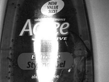
Figure 2A
Coaxial Ring Light RL1424
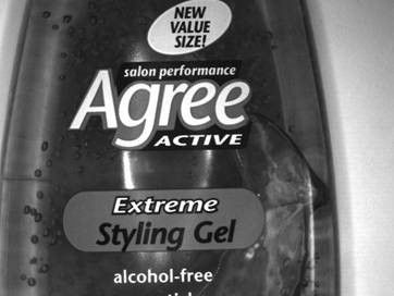
Figure 2B
Coaxial Ring Light with Polarizer RL1424
A polarizer set with one element mounted on the light (polarizer) and the other mounted on the camera lens (analyzer) was applied to block glare. This is potentially an adequate result (Fig. 2B), although some glare can still be seen.
And because polarization may significantly reduce the amount of light reaching the lens, the light output or system exposure times need to be increased correspondingly. This circumstance can also create an under-exposure situation in hi-speed parts inspections, which may be light-starved already.
However, polarization may be ineffective if the bottle shape, size, or orientation changes, or if the incident light angle is modified. A more robust solution would be a change in the 3-D geometry among part, light and lens. In this case, (Fig. 2C, below) the light was moved off-axis and the image is now completely free of specular reflections. Fig. 2D illustrates the lighting function diagram and 3-D geometry deployed.
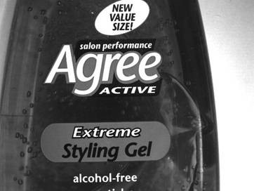
Figure 2C
Off-Axis Ring Light without Polarizer RL1424

Figure 2D
Off-Axis Ring Light Geometry

Figure 3A
White Ring Light RL4260

Figure 3B
UV 395 nm Ring Light RL4260
Example: Motor Oil Bottle Inspection
The motor oil bottle sample (Figs 3A – 3B, above right) was originally illuminated with a white light, effectively imaging the dot-matrix printed lot code on the bottle. However, under UV light, we see that another, covert lot or date code is now visible and not otherwise obvious under visible light.
Example: Using Color for Image Contrast
Printed postage stamps for commercial mailer envelopes are typically printed with either red or black ink and are subsequently inspected under red or white light – the 2 most common vision light colors. For example, illuminating a black printed stamp under either red or white light will generate excellent print contrast similar to that seen in Fig. 4A.
However, illuminating a red stamp under red light effectively generates no contrast (Fig 4B), therefore the system cannot read the stamp. A red light solution was adequate or good enough for certain colors, but not robust enough for all situations. And while still a compromise, white light provides a more comprehensive solution for all print colors (Fig. 4C).

Figure 4A
Green Stamp under Red Light
(Similar contrast as a black stamp under
white or red light)

Figure 4B
Red Stamp under Red Light

Figure 4C
Red Stamp under White Light
(Note less contrast than Fig. 4A)
Another common inspection example using color for contrast: reading or verifying a purple dot matrix print on the concave bottom of an aluminum soda can. Fig. 5A illustrates a barely adequate image obtained with a Coaxial Diffuse Light (see Fig. 5B for the light geometry function diagram). In this instance the image is acceptable, but only if every print is centered through the middle of the can. Using a diffuse dome technique (Figs 5C – 5D), we obtain a more robust solution, which allows the vision system software to read or verify the print regardless of its location on the can bottom.

Figure 5A
Coaxial Diffuse DL225-050

Figure 5B
Coaxial Light Function Diagram

Figure 5C
Diffuse Dome DL2230

Figure 5D
Diffuse Dome Light Function Diagram
Importance of Testing and Control in Machine Vision
As we have seen, what might appear to be an “adequate” lighting solution can turn out to be insufficiently robust to account for all the part differences encountered. The simplest method for avoiding this problem is to test many parts – ones that include any possible sizes, shapes, orientations, colors/textures and presentations before settling on a lighting type. And it’s important to include “good” and “bad” parts, especially those that are borderline pass/fail. Finally, it is also beneficial to have good control over ambient light by using either physical shrouding, or a narrow-band colored light and a matching pass filter.